![]()
Customized mini pc included industrial pc, htpc and thin client
Mini-itx motherboard, dom, ssd, pc chassis and power supply
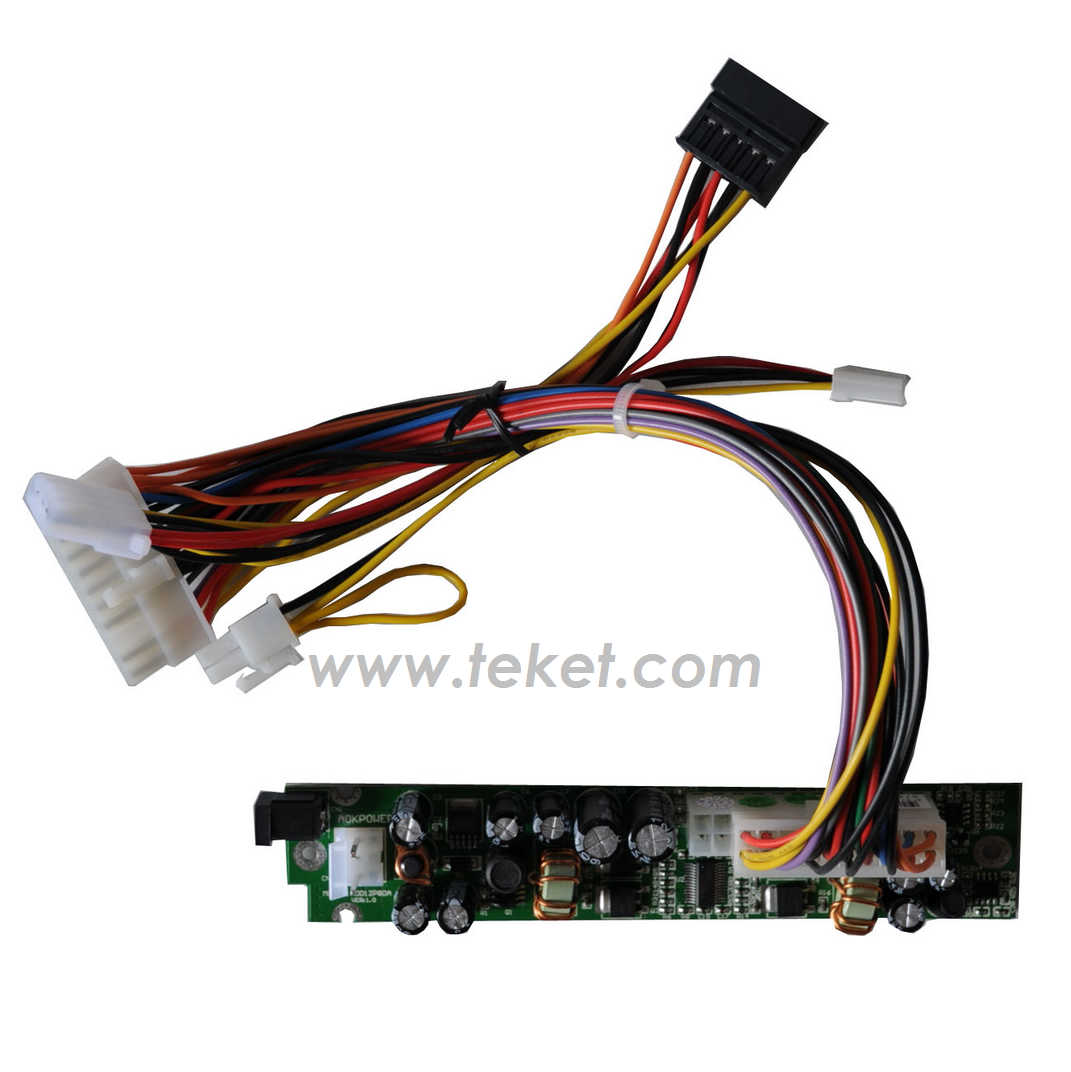
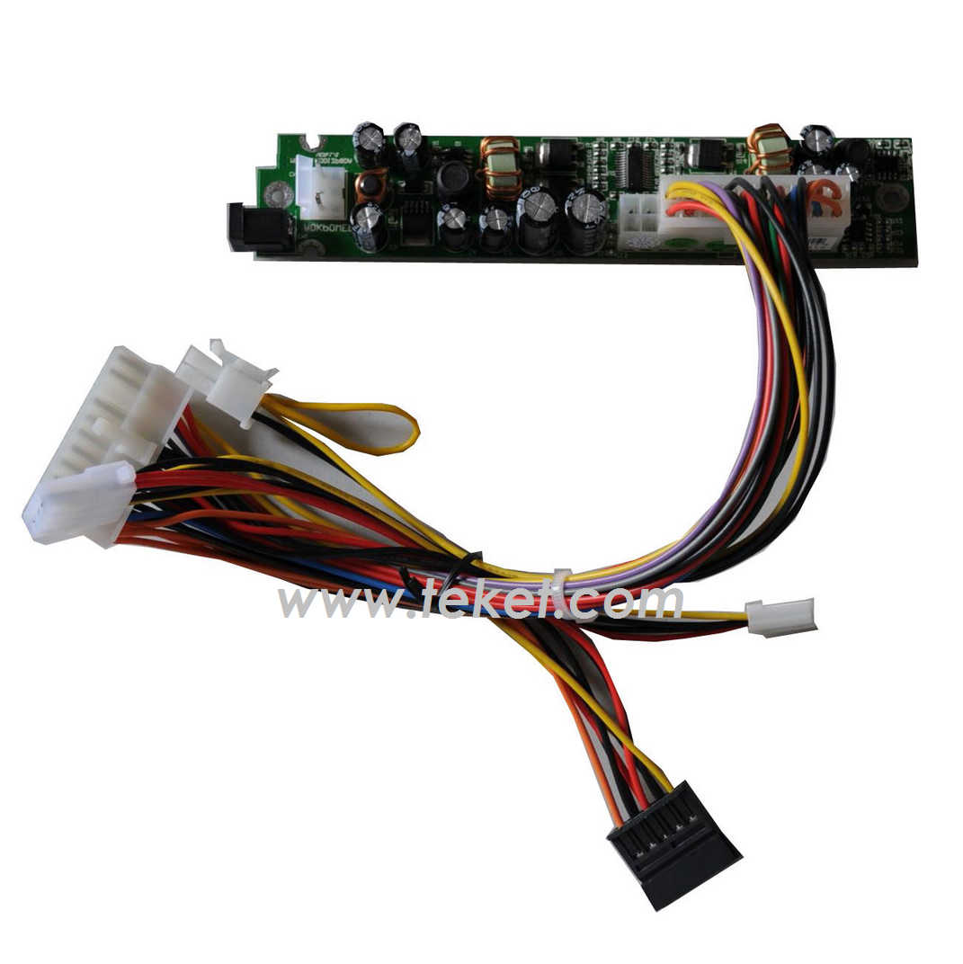
-->> ATX power supply board 12VDC Input 80W DC to ATX Convertor <<--
12VDC Input 80W DC-ATX ConvertorThis specification defines the performances and characteristics of a 87 watts,5 output level DC to DC converter for use in ITX computer system product.
1,Input Requirements:
Vin: Minimum=11.4vdc,Maximum=12.6vdc,Nominal=12.0
Ripple & Noise: 200 mVp-p
2,Efficiency:
The converter efficiency should not be less than 90% at the maximum load
with nominal DC input voltage.
3,Output Power Distribution:
Load Current (A),
+12V: Maximum=4,Peak=5
+5V: Maximum=4,Peak=7
+3.3V: Maximum=4,Peak=7
-12V: Maximum=0.1,Peak=0.2
+5VSB: Maximum=1,Peak=2
Maximum Combined Power (W): 87, At max combined power 140W, a fan is required.
4,Output Voltage Regulation:
+12V,+5V,+3.3V and +5VSB: ¡ᄉ%
-12V: ¡ᄆ5%
5,Output Ripple and Noise:
Ripple and noise are defined as periodic or random signals over frequency
band of
10Hz to 20MHz. Measurement shall be made with an oscilloscope with 20MHz
bandwidth. Output should be bypass at the connector with a 0.1uF ceramic
disk capacitor and a 10uF electrolytic capacitor to simulate system loading.
Maximum Ripple & Noise ( mVp-p)
+12V: 120
+5V: 50
+3.3V: 50
-12V: 200
+5VSB: 50
6,+5VSB Output:
The +5VSB is a standby supply output is active whenever the DC input is
present.
7,DC Output:
This DC output +5VSB is controlled by the DC input, but the other DC output
is controlled by the "PS-ON#" signal and DC input.
8,Overshoot and Undershoot:
Any overshoot at turn on or undershoot at turn off shall be less than
¡ᄆ0% of the nominal output voltage values.
9,Power-on Time:
The Power-on time is defined as the time from when PS-ON# is pulled low
to when the
+12VDC, +5VDC, and +3.3VDC output are within the regulation range specified
in section
3.2. The power-on time shall be less than 500ms (T1£¼500ms).
10,Rise Time:
The output voltage shall rise from 10% of nominal to within the regulation
ranges specified
in section 3.1 within 0.2ms to 20ms (0.2ms¨QT2¨Q20ms).
11,Power Good Signal:
PS-ON# is an active-low, TTL-compatible signal. When PS-ON# is pulled
to TTL low, the converter should turn on the four main DC output rails:
+12VDC, +5VDC, +3.3VDC,
and ¨C12VDC. When PS-ON# is pulled to TTL high or open-circuit, the DC
output rails
should not deliver current. PS-ON# has no effect on +5VSB output, which
is always enable whenever the DC input is present.
Logic level£º
"High" is 2.0V ~ 5.25V
"Low" is 0.0V ~ 0.8V
12,Over Voltage Protection:
When the +12VDC, +5Vdc, and +3.3VDC output have over voltage condition,
the converter shall provide latch mode over voltage protection
13,Short Circuit Protection:
An output short circuit is defined as any output impedance of less than
0.1 ohms. The
converter shall shut down and latch off for shorting the +3.3VDC, +5VDC,
or +12VDC rails
to return or any other rail. Shorts between main output rails and +5Vsb
shall not cause any damage to converter. The converter shall either shut
down and latch off or fold back for shorting the negative rails. +5Vsb
must be capable of being shorted indefinitely, but when
the short is removed, the +5Vsb output shall recovery automatically or
by cycling PS-ON#. The converter shall be capable of withstanding a continuous
short-circuit to the output
without damage or overstress to the unit.
14,Over Power Protection:
The converter can use electronic circuit to limit the output power against
excess 140W of surge power or protected against excessive power delivery
at section 6.1 temperature environment due to short circuit of any output
or over total power at any input condition.
15,No-load Operation:
No damage or hazardous condition should occur with all the DC output connectors
disconnected from the load. The converter may latch into the shutdown
state.
16,Reset After Shutdown:
If the converter latches into a shutdown state because of a fault condition
on its outputs, the converter shall return to normal operation only after
the fault has been removed and
PS_ON# has been cycled OFF/ON with a minimum OFF time of two seconds.
17,Environment:
Operation Temperature: 0 ¡to 40 ¡⁼br>
Relative humidity: 10% to 90%, non-Condensing.
Shipping and storage Temperature: -40 ¡to +70 ¡⁼br> Relative humidity: 5% to 95%, non-Condensing.
18,Reliability:
The demonstrated MTBF shall be 100,000 hours of continuous operation at
25¡ full load, 80% confidence limit and nominal line. The MTBF of converter
shall be calculated in accordance with MIL-STD-217D/E. The DC Fan is not
included.
Burn-in Test: The power supply shall be 100% burn-in tested with maximum
loading and 40 ¡⁼br>
environment temperature.
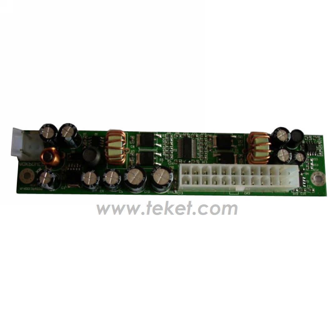
19,Mechanical Specification:
Weight: The converter weight: about 45 grams.
Layout: 145mm x 30mm
BEIJING: 1 Information Road, Shangdi, Haidian, Beijing 100085, China
Tel: 0086-10-82894738 Fax: 0086-10-82893738
HONG KONG: Room 504, President Commercial Centre, 602-608 Nathan Road, Mongkok, Kowloon, Hong Kong
Tel: 00852-2781-6070 Fax: 00852-2781-6078